Looking Closer at Resonant Capacitors in Electric Vehicles
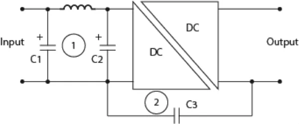
One of the primary goals in electric vehicles (EVs) is to increase the efficiency of its power conversion devices. The more efficiently power is converted, the further distance the EV can travel on one charge. For example, by reducing losses in a DC-to-DC (or DC/DC) converter, the converter (and overall vehicle) benefits from improved energy efficiency, a more streamlined design, and diminished heating from components.
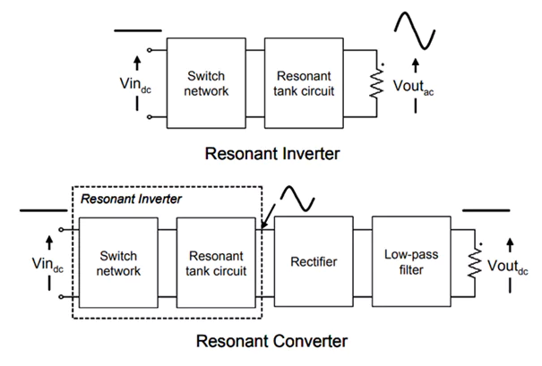
There are many types of DC/DC converters, and in this article, we’ll be focusing on resonant DC/DC converters. Resonant converters are switching-based converters that incorporate a resonant tank for controlling input-to-output power flow. Resonant converters are commonly used in high-voltage applications to smooth waveforms, improve power factor, and reduce switching losses caused by high-frequency power switches (such as MOSFETs and IGBTs). In particular, the LLC circuit is popular choice for executing a resonant converter because it achieves zero voltage switching (ZVS) and zero current switching (ZCS) over the entire operating range, supports higher switching frequencies, decreases component footprint, and reduces electromagnetic interference (EMI).

Figure 1. Block diagram of a resonant converter (source: STMicroelectronics)
Resonant converters are built on a resonant inverter that uses a switching network to convert the DC input voltage into a square wave, which is then applied to the resonant circuit. As seen in Figure 2, this resonant tank consists of a resonant capacitor Cr, resonant inductor Lr, and the transformer’s magnetizing inductance Lm– all connected in series. The LLC circuit is responsible for filtering out any higher order harmonics by selectively absorbing maximum power at the specific resonant frequency of the square wave and releasing a sinusoidal voltage via magnetic resonance. This AC waveform is scaled up or down by the transformer, rectified, and then filtered to produce a converted DC output voltage.
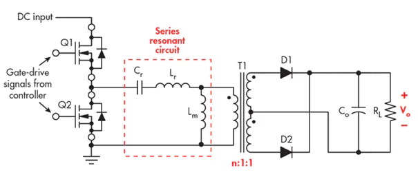
Figure 2. Simplified LLC resonant DC/DC converter (source: Electronic Design)
When it comes to selecting the right resonant capacitor Crfor DC/DC converters, the root mean square (RMS) current of the capacitor is one of the most significant parameters to consider. It impacts capacitor reliability, voltage ripple, and overall converter performance (depending on the resonant circuit topology). Heat dissipation is also affected by the RMS current and other internal losses.
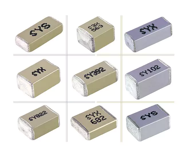
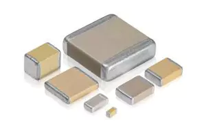
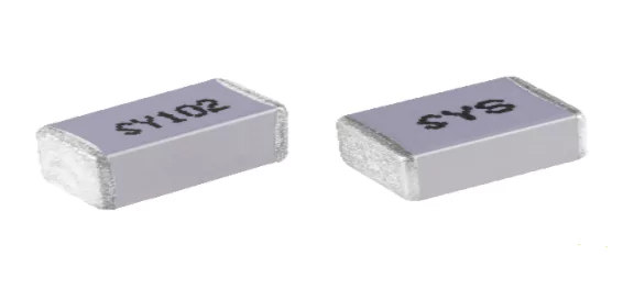
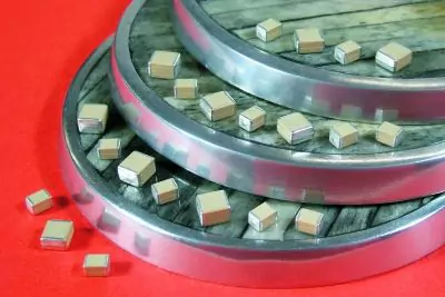
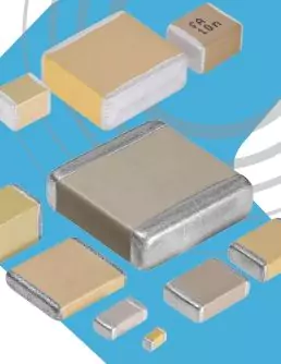
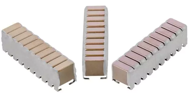
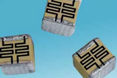
In fact, self-heating in capacitors is a universal concern in EV converter systems and other high power applications. For resonant capacitors, we typically recommend multilayer ceramic capacitors (MLCCs) with very stable capacitance, tight tolerances, and low dissipation to prevent overheating, such as our 500V-1kV 4.7nF-39nF C0G capacitors.


